|

Czech Model's 1/48
scale XP-55 Black Bullet is available online from Squadron.com
S
u m m a r y
|
| Catalogue Number: |
CM4808 |
| Scale: |
1/48 |
| Contents and Media: |
31 parts in short-run injected grey styrene;
30 parts in cream-coloured resin; 2 clear parts on a vacform sheet; decals for
one aircraft. |
| Price: |
USD$24.96
from Squadron.com |
| Review Type: |
FirstLook / Partial Construction |
| Advantages: |
Appealing subject; high-quality
plastic; good detail; clean, crisply engraved surface detail; effective
use of multi-media; very good fit for short-run kit. |
| Disadvantages: |
Exhaust stacks not represented; some
difficult resin casting blocks. |
| Recommendation: |
Recommended to modellers with some
experience working with short run kits. |
Reviewed by
Brett Green
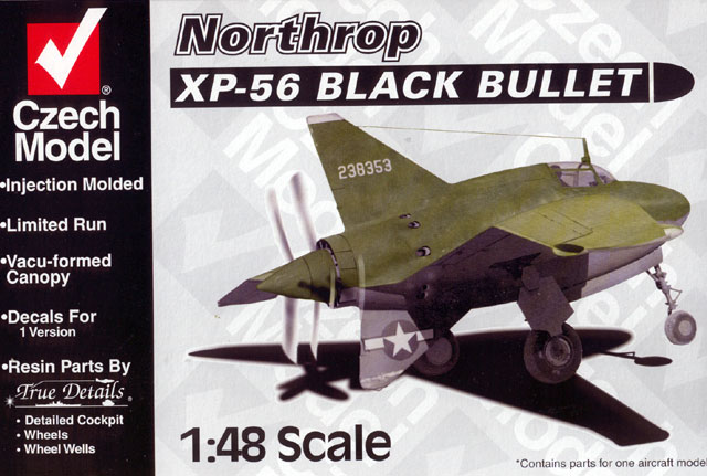
The Northrop XP-56 "Black Bullet" was one of three responses to a 1940
proposal for a high-speed, heavily armed fighter aircraft.
This distinctive design included a rear-mounted Pratt & Whitney R-2800-9
engine driving counter rotating propellers pushing the aircraft from the rear.
Long, swept wings with an anhedral kink at the outer edge provided a stark
contrast to the stubby, bullet-like fuselage. Further oddities on the second
prototype included the absence of a rudder. Instead, directional steering was
supplied by blown-air jets in the wingtips!
As implausible as the design might sound, two XP-56 prototypes were built and
flown. The first was irreparably damaged after its fourth flight in October,
1943. The second prototype flew on ten occasions, and survives today at the
National Air and Space Museum.
This second prototype is the subject of Czech Model's new kit.
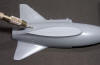
Czech Model's 1/48 scale XP-56 Black Bullet comprises 31 parts
in grey styrene, 30 parts in cream-coloured resin, two vacform canopies (a spare
is provided) and decals for the single aircraft.
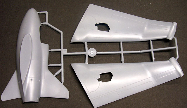
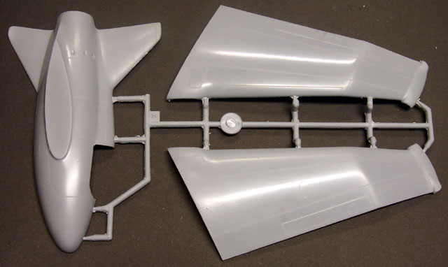
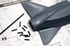
The first impression is very good. The quality of the plastic is
high, and surface detail is crisply engraved. Flash is almost non-existent but
the sprue connection points are quite thick. The trailing edges of the fins and
wings are admirably thin - no additional work is required here. Another nice
touch is the bevelled opening for the undercarriage in the lower wings.
Resin parts are supplied for the detailed cockpit, wheel wells,
rear spinner, wing root radiator intakes, wheels and a few other details such as
pitot tube and antenna mast. These resin parts are very well done - detail is
crisp and my sample displayed no casting imperfections. However, a number of
parts feature chunky casting blocks that require time and care to remove. Other
parts are quite delicate, and can be easily damaged when being removed.
Click the thumbnails below to view
larger images:
A vacform canopy is supplied with a spare in case of disaster.
The canopies are very clear and totally free of distortion. However, there is no
indication of how the canopy opens (ie where does it hinge etc).
Engineering is typical of a limited run kit. The long wings
mount flat against the fuselage, but the surface area of the join will be quite
large so reinforcement may not be required. There are no locating pins, and a
few details are missing due to the limitations of the low-pressure injection
moulding process. The most obvious omission is the ring of exhaust ejector
stacks around the mid-rear of the fuselage.
Instructions are supplied over four letter-sized pages in twelve
construction steps. These instructions are okay, but there is a quite a lot left
for the modeller to discover for himself.
We can be fairly confident that a new release from Tamiya,
Hasegawa or Revell will be straightforward to assemble and will fit quite well
without modification. The same cannot always be said of limited run kits.
In this case, however, I can report that the fit of this kit is
excellent with the application of appropriate care and preparation.
Following extensive test-fitting and assembly of components, I
can offer the following suggestions to modellers planning to build this
interesting aircraft:
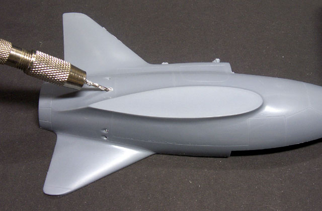
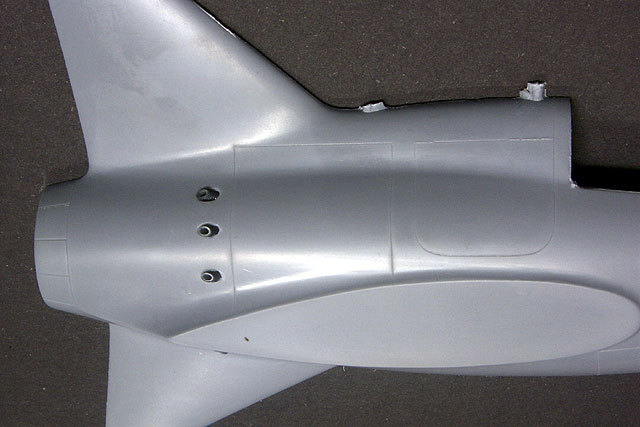
Adding Exhaust Stacks
I wanted to depict the prominent ring of exhaust ejector stacks
around the rear fuselage. I decided to tackle this as the first construction
task using the following process:
Click the thumbnails below to view
larger images:
|
|
|
|
Using the dents on the kit fuselage as a guide, holes were drilled at an angle
|
|
|
|
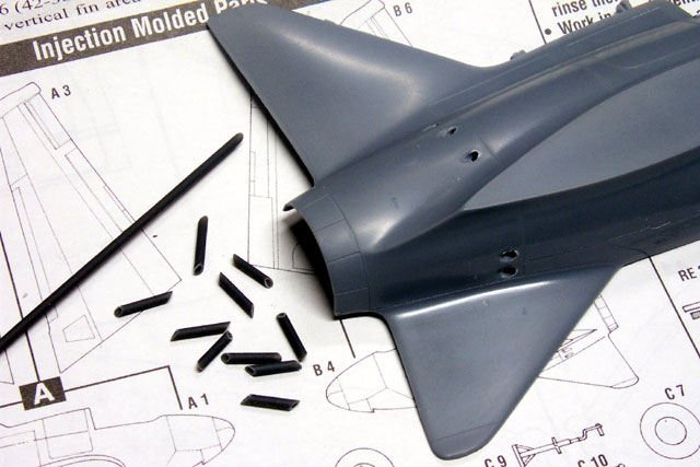
Contrail .020" plastic tube was sliced into short lengths with the ends cut at a 45 deg. angle, then inserted in the holes
|
|
|
Steps 1, 2 & 3 - Cockpit and
Fuselage
Czech Model supplies a very detailed resin cockpit with the kit.
Take special care when removing the seat from its block. The
entire block must be removed, but I sawed through the bottom of the seat during
removal. I also damaged the instrument coaming when scoring this away from its
block.
I suggest the following sequence for preparing and assembling
the cockpit and fuselage parts:
-
Sand down the resin waste on the
bottom of the cockpit floor (part no. RE 2).
-
Glue the seat (RE 5) to the rear
bulkhead (RE 1).
-
Glue the cockpit floor (part no. RE
2) to the bulkhead (RE 1) at a 90° angle. The bottom
of the seat should be resting on the raised perforated casting on the rear of
the cockpit floor.
-
Add the trim wheel (part RE 6) after
this assembly has dried. If it is added before, it may foul with the seat when
it is glued in place.
-
Don't glue the sidewalls in
place yet.
-
The rear bulkhead has a cutout on
the bottom half. This acts as a saddle for the forward wheel well (part RE
11). Slip the bulkhead over the back of part RE 11, then dry fit the combined
assembly in the port (left) side fuselage half. Adjust the parts until the
cockpit and the wheel well are in the correct position, then use a spot of
super glue to tack the pieces together. Don't glue them to the fuselage yet.
|
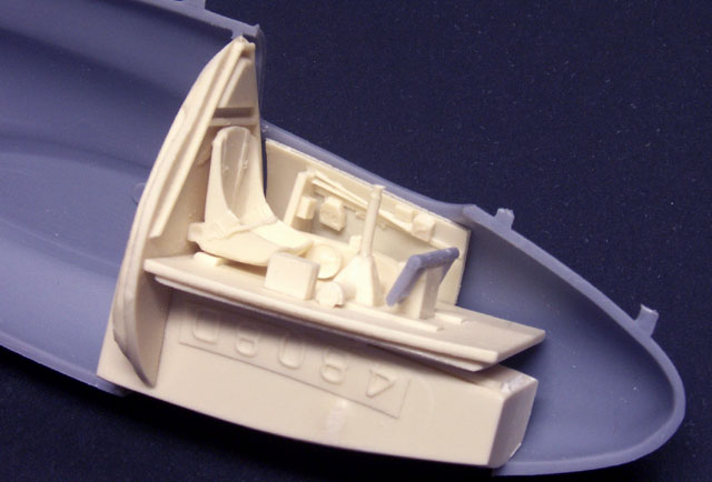
|
|
The
cockpit/wheel well assembly being test-fitted to the fuselage.
The port-side sidewall is temporarily attached to the fuselage side with Blu-Tack. |
-
Test fit the fuselage halves by
trapping the loose cockpit/wheel well assembly. Note any areas that need
adjustment or trimming and correct these now.
-
This will be a good time to paint
the cockpit, sidewall and wheel well sub-assemblies.
-
According to your personal
preference, you can now either glue the painted sidewalls to the cockpit
sides, or test fit them against the fuselage interior.
-
Don't forget to allow for nose
weight.
A large ejector pin must be totally removed from the starboard
sidewall before the cockpit can be glued inside the fuselage.
Test-fitting suggests that the fuselage halves will deliver a
totally gap-free join.
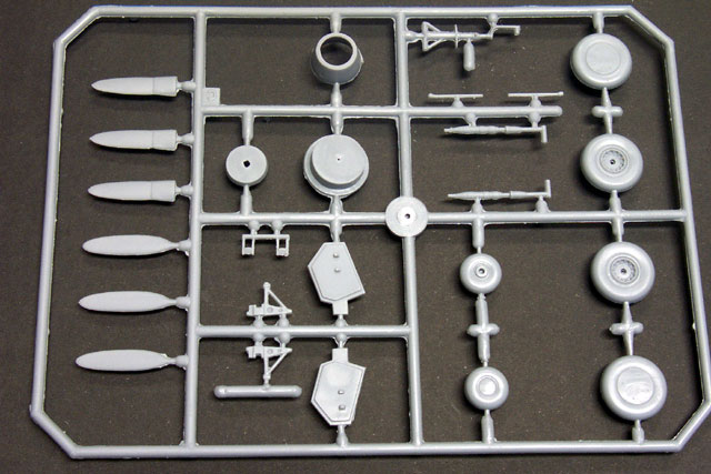
Steps 3, 4 & 8 - The Propeller
Assembly
The counter-rotating propeller is one of the key distinguishing
features of this model. According to the instructions, the entire assembly can
be made to rotate but I was not that ambitious.
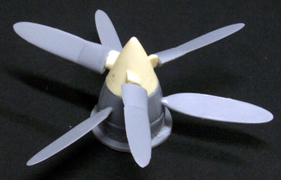 The
propeller blades are nicely formed in styrene. They are attached to the sprue at
the base, Take care not to chop off too much of the base - you'll need some of
sprue connectors as locating pins for the spinners. Once the propeller blades are removed
from the sprue, carefully clean up the locating pin with a sharp knife and a
sanding stick. The
propeller blades are nicely formed in styrene. They are attached to the sprue at
the base, Take care not to chop off too much of the base - you'll need some of
sprue connectors as locating pins for the spinners. Once the propeller blades are removed
from the sprue, carefully clean up the locating pin with a sharp knife and a
sanding stick.
The rear spinner is supplied in resin. The locating holes are
quite deep and adequate for a strong bond. However, care is once again required
removing the casting block.
The positions for the holes in the forward spinner (plastic part
C 17) are simply indicated by three shallow dents. I drilled these holes using a
2mm twist drill.
The propeller blades were glued in place. Remember that these
were counter-rotating (ie they rotated in opposite directions to each other) and they
pushed the aircraft (so the pitch is the reverse of what we would see on a
conventional model).
When the propeller blades were dry, I glued the resin rear
spinner (RE 12) to the forward spinner (C 17), and the forward spinner to part C
16. I ignored part C 18, the forward spinner backplate, because my propellers
were fixed in place.
When the propeller assembly is secured to the fuselage, I will
add actuator rods for the cowl vent flaps. I plan to use styrene or brass rod
for this task.
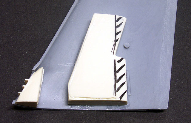
Steps 6 and 7 - Wings and Wheel
Wells
The inside surfaces of the wings have several prominent ejector
pins that should be removed before assembly.
The resin wheel wells each have a large casting block. Most of
this block needs to be removed, with special emphasis on the rear of the block
(note the shaded area in the image below). Test fit this part frequently to
ensure it does not foul with the upper wing.
The casting block for the resin radiator intake is simple to
remove by comparison. The fit of this parts was perfect straight off the block.
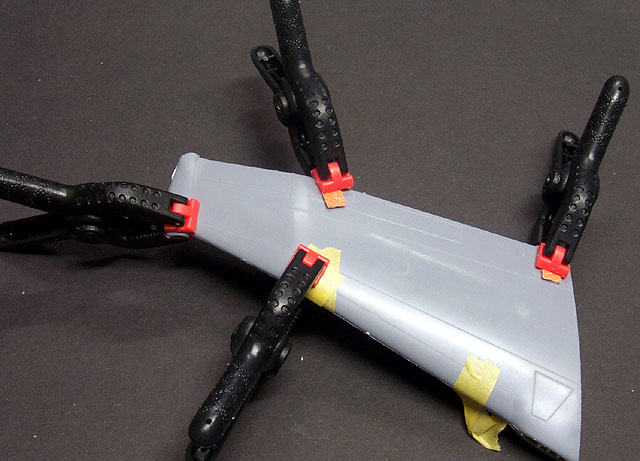
The interior of the blown-air jets at the wingtips is empty. The
result is an undesirable see-through effect. I rolled a ball of Milliput to
blank off the interior before mating the wing halves. After taping and clamping,
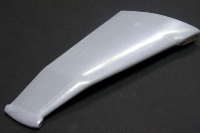
the assembled wings fitted perfectly in spite of their relatively complex shape.
The trailing edges are also admirably thin with no extra effort.
Click the thumbnails below to view
larger images:
Czech Model's 1/48 scale XP-56 Black Bullet is an impressive
limited-run model.
It will require a little extra time in preparation and assembly,
but will deliver a very different looking model when it is finished. Anyone with
some experience of limited-run kits should be capable of completing this kit
without much trouble.
Recommended.
Thanks to Squadron.com for the review sample.
Review and Images Copyright © 2002 by Brett
Green
Page Created 25 February, 2002
Last updated 22 July, 2003
Back to HyperScale Main Page
Back to Reviews Page
|
 Home | What's
New | Features
| Gallery |
Reviews | Reference
| Forum
| Search
Home | What's
New | Features
| Gallery |
Reviews | Reference
| Forum
| Search